WL-8592 - "WEIRD VECTOR"
MATERIALS GUIDE
SUPPORT
If any issues arise please click here to contact us via email first. We'll walk you through any problems you may be having (with the module).
B.O.M.
for v2.0 (SMD) boards
| Part | Value | Qty. | Link | Other Notes |
|---|---|---|---|---|
| T1 / T2 | BC847C | 2 | here | |
| Q2 | MMBT3906 | 1 | here | |
| D1 to D7 | 1N4148WX | 7 | here | |
| LED1 / LED2 | TSAL7400 | 2 | here | PCB footprint for LEDs has room to replace IR LEDs with normal diodes, if preferred. |
| R1 to R16 | 10k | 16 | here | 1/8w 0805 SMD |
| C1 | 1uf | 2 | here | 50v 1206 SMD |
| All Jacks | 16 | here | aka "Thonkiconn" - Tayda is out of stock occasionally, in which case try Thonk.uk |
for v1.0 boards
| Part | Value | Qty. | Link | Other Notes |
|---|---|---|---|---|
| T1 / T2 | 2N3904 | 2 | here | Probably could get away with other NPN transistors (BC547 for example) - experiment, but at your own risk. |
| Q2 | 2N3906 | 1 | here | |
| D1 to D7 | 1N4148 | 7 | here | |
| LED1 / LED2 | TSAL7400 | 2 | here | PCB footprint for LEDs has room to replace IR LEDs with normal diodes, if preferred. |
| R1 to R16 | 10k | 16 | here | 1/4w, 1% metal film resistors preferably. |
| C1 | 1uf | 2 | here | Solder one capacitor on the front side of the board, and the other on the back. |
| All Jacks | 16 | here | aka "Thonkiconn" - Tayda is out of stock occasionally, in which case try Thonk.uk |
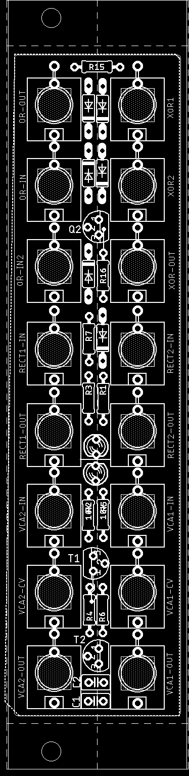
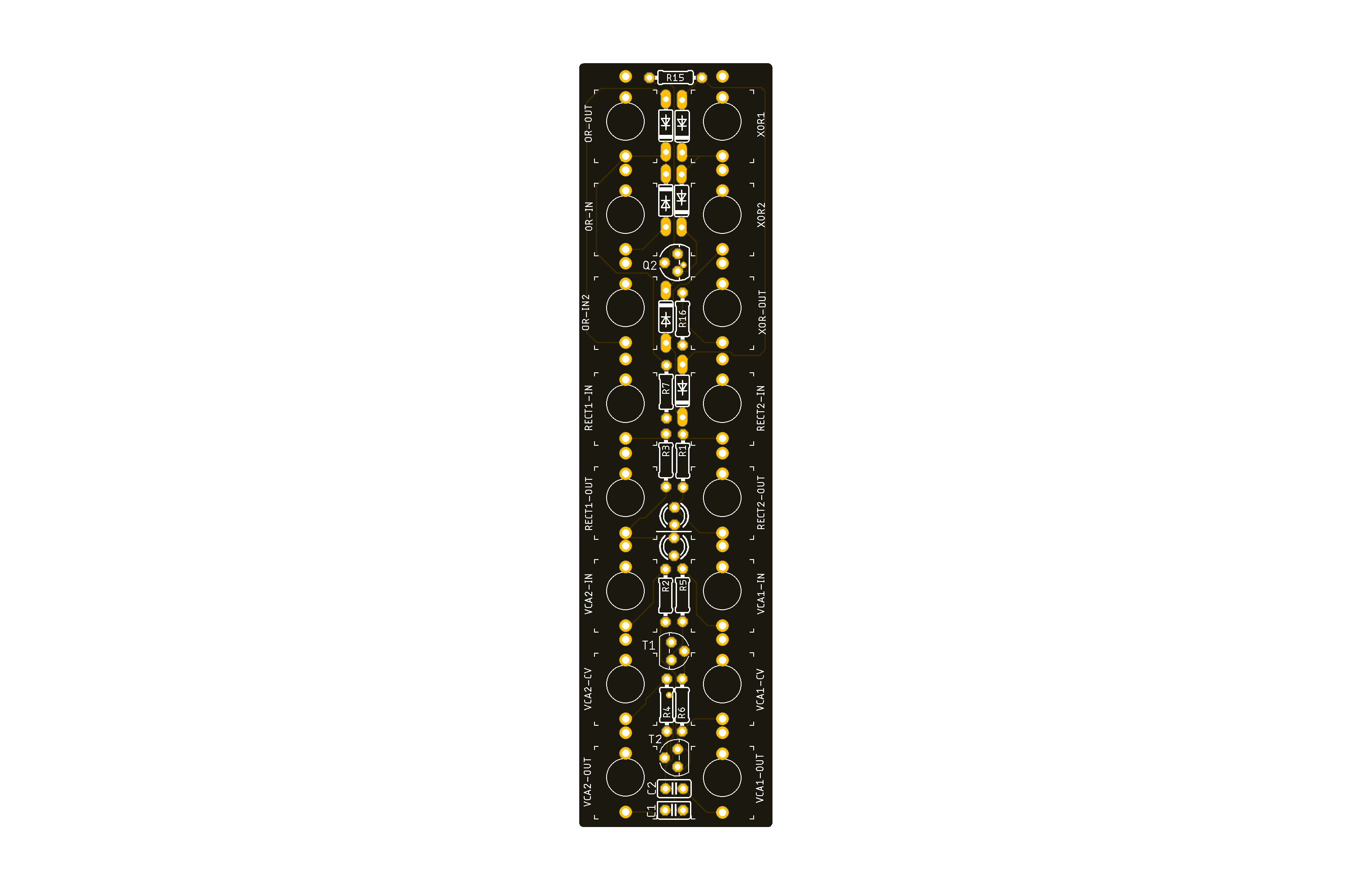
BUILD NOTES
-
The LED placement location is above R2 and R5 - orient the flat side of the LEDs to the flat side of the silkscreen
-
This is a tightly packed module - place the smaller components first, and the jacks last. You may have to (gingerly, gently) move some components out of the way if they bump up against the jacks, but for the most part we've done a pretty good job in the space efficiency department.
-
Solder one capacitor on the front side of the board, and the other on the back. This is a neccessary step to get the slightly larger 1uF MLC (multilayer ceramic) capacitors on the board.
-
Since it's passive, power is not needed, and thankfully you won't have to check for shorts!